
Project 1: Power Transmission
MECH 2112 – Fundamentals of Mechanical and Computer-Aided Design
March 17, 2022
Group 11
Ben Fransoo
Evan Palles
Iverson Pasco
Jeremy Baker
Kealan Barkman
Table of Contents
1. Introduction
Overview of the project, primary goals
2. Design Parameters
Values found, excel sheet graphs, parameters
3. Power Transmission Design
Ratios, and gear/belt/chain reasoning
4. Detailed Design
Shifting method, motor attachment, frame attachment, etc. WDM’s
5. Prototype Summary
Description of prototype and CAD model
6. Overall Summary
How prototype functions and main concerns with the design
7. References
8. Appendices
- 8.1 Cost Analysis
- 8.2 Equations
1. Introduction
The primary goal of this project is to design the power transmission for a small, two-wheel, single rider, moped-style vehicle. This vehicle should be designed to travel on railway tracks where both wheels travel along the same rail. The project only involves designing the gearbox portion of the powertrain. The 3-speed gearbox must attach to the provided moped frame and accommodate a BDC-1921 brushless DC motor and pedal power input from the rider. In addition, the gearbox must be capable of shifting using at most two motions.
This project has several secondary goals, including determining a reasonable acceleration, coefficient of drag, frontal surface area, and other related parameters to calculate the power required for the design to operate at speeds up to 100km/h. The power transmission system must be designed using 2D and 3D parts and a CAD model of the powertrain system with functioning mates. Finally, a physical prototype must be built to show the functionality of the design. A more detailed description of the project overview can be found in the project outline [1].
2. Design Parameters
When beginning the process of creating the vehicle, background knowledge was obtained to narrow down the project’s scope. The research was done to find the values for the drag coefficient (Cd) [2], rolling resistance coefficient (Crr) [3], maximum grade of train tracks [4], frontal area (Af) [2], air density [5], human bicycle power output [6], average acceleration of a bike [7], bike weight [8]. These values were used [Eq. 1-4], to find the minimum power required for the bike to achieve 100 km/h, this would become a general estimated power for our motor to start with.
The next step was to use angular velocity at the corresponding power value to find the conversion ratio [Eq. 5] to find the torque of the motor [ Eq. 6]. The velocity also needed to be derived [Eq. 7] to create a power (W) vs. velocity (m/s) graph, which made it possible to visualize the process. Using this graph and overlapping it with a second line affected by average acceleration and the previous linear torque pattern enabled the values to be tweaked to find the reduction values of the three gear ratios.
Since the project uses a BDC motor, it was found that the motor operates at a maximum efficiency of 80%. Therefore, the reduction value found for the third gear reduction only uses the values found at 80% on the torque line. For the first reduction, the value of 20 was found when the speed is at half of the maximum speed (50 km/h or 13.89 m/s), as shown in Figure 1. The second reduction of 15 made the vehicle accelerate to the top speed, purely on the motor’s power. This can be seen in Figure 2. The third reduction of 10 was found to maintain the maximum speed of 100 km/h operating at the motor’s maximum efficiency, along with a power input from a human pedalling at a reasonable rate. This can be seen in Figure 3. The average power output of a human biking widely varies from person to person, with a generally athletic human producing around 200 to 400 W [9]. In order to make the vehicle accessible for as many people as possible, 100 W was used as the human power value.


3. Power Transmission Design
Having found the three reductions previously discussed in the design parameter section, the next objective was to figure out the layout and gear ratios needed for the gearbox. Gear ratios were required to be less than or equal to 2.5:1, as stated in the constraints of the project. Therefore, the reductions were broken down in the following manner:
10 – 2.5:1, 2:1, 2:1, 1:1
15 – 2.5:1, 2:1, 2:1, 1.5:1
20 – 2.5:1, 2:1, 2:1, 2:1
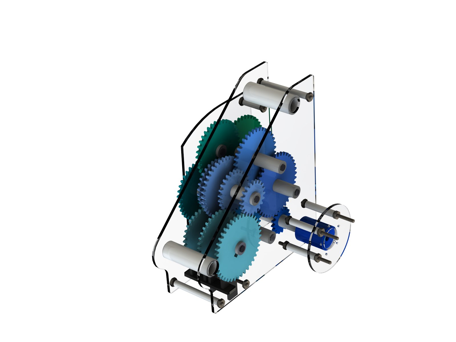
Since the reductions contained many of the same ratios, there was the opportunity to condense the transmission so that the reductions could share the first three gear ratios and therefore share the same shafts. This was why gears were used instead of chains or belts, as it saved space, cost, and effort in coming up with the layout. All gears used had a common circular pitch of 5 and a pressure angle of 20. In the end, there were five shafts needed for the main portion of the transmission. The first was in line with the input containing a 2.5:1 ratio between a 16 and a 40-tooth gear. The second and third shafts were situated in a row and contained a 2:1 ratio between 18 and 36 tooth gears. The final two shafts diverged in direction, with the shaft containing the 1:1 ratio having gears with 30 teeth each. The other shaft contained both the 1.5:1 ratio between gears of 24 and 36 teeth and the 2:1 between gears of 20 and 40 teeth.
For the second part of the gearbox that mates the pedal power to the output shaft, there is a reverse process with a reduction ratio of 1:10 to slow down the rotation speed of the pedals so the person operating can bike along with the motor. A separate system of gears started with a 1:1 ratio between two 32-tooth gears, reversing the direction so that the last gear could mesh with the gear on the shaft before the output shaft in the main portion. The second ratio is 1:2.5 between 16 and 40 tooth gears. This is followed by two 1:2 ratios between 18 and 36 tooth gears, with the final ratio meshing with the main portion, as mentioned before.
4. Detailed Design
Many aspects needed to be carefully considered when designing our gearbox, one of which was how the shifting mechanism should function. Since there were three reductions, we used dog clutches to choose which ratio we wanted to use at a specific moment. These dog clutches operated with a hex-shaped hole in the center and a square protrusion coming from the side to latch onto the desired gear. The gears on the final shaft have circular holes that enable them to spin freely, unaffected by the shaft, unless attached to a dog clutch. The dog clutches are moved by wrenches that have a bolt through them to keep the wrenches in place to shift between gears.
Another aspect we discussed thoroughly was the method and location we should mount the motor. The method of mounting the motor was solved rather quickly as the detailed sketch provided for the motor clearly indicated five mounting holes which could be used to mount the motor to the gear wall. A more general problem was whether the motor should be mounted inside or outside the gearbox. We decided to mount the motor outside because it freed up space inside the gearbox.
A third aspect was how to mount the gearbox to the frame. One of the nuisances we encountered was simply modelling the frame accurately to ensure there were no clearance issues when mounting the final gearbox. We managed to sidestep many of the challenges by setting maximum clearances around the bolt holes and forgoing the third mounting hole. Given the risk of our gearbox not fitting if there was an error in our measurement, we decided to forgo the third mounting hole. We concluded that using two mounting holes was more than sufficient to mount the gearbox to the frame securely.
After calculating the appropriate gear ratios, we started with the smallest gear available with ten teeth and attached it to a 25-tooth gear to get our first 2.5:1 ratio. For the following ratio, we needed a 2:1 ratio, but a 10 to 20-tooth gear left one of the axles going through the 25-tooth gear. Therefore we decided to go to 36 and 18-tooth gears. The other gears for the 2.5:1 ratio became 40 and 16-tooth gears, which also worked with this change.
The gear walls were designed based primarily on the gear alignments and the mounting points. The bolts were then placed in areas that would not interfere with the frame or gears.
Table 1: Weighted Decision Matrix for Mounting to the Bike 
Table 2: Weighted Decision Matrix for the Motor Mount
5. Prototype Summary
The prototype was designed primarily around the mounting points. The mounting points were measured and then used to construct a gear wall that outlined how much room we’d have for the gear shafts. Once the gear ratios were determined, appropriate gear sizes were selected and used to make a map of where the shafts were going to be.
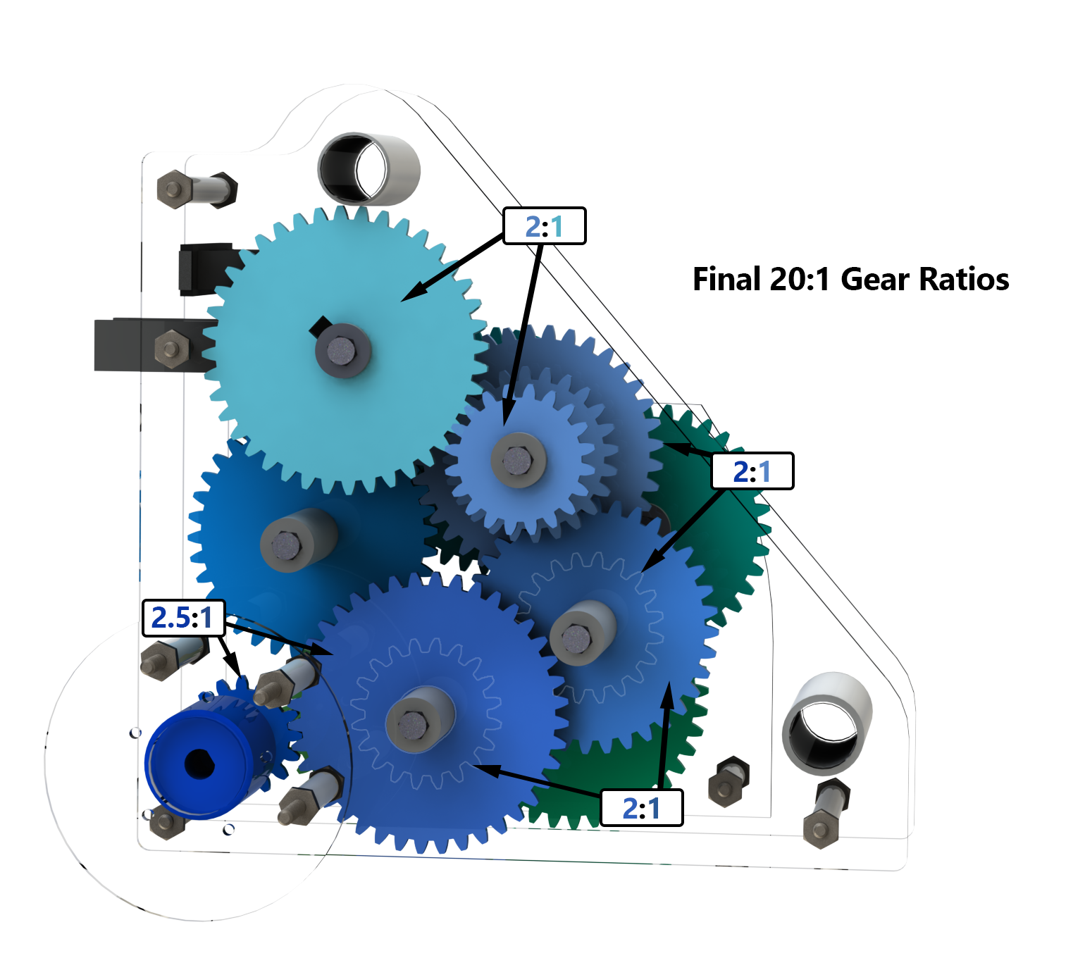
A traditional clutch would have been outside the project’s scope, so our team decided to use a dog clutch mechanism. The gears on the dog clutch system have circular holes and sit on a hex shaft, so when the shaft is spinning, the gears do not move with the shaft. When the user wants to engage a gear, they slide the gear shifter along the hex shaft until a single tooth from the end of the shifter engages with the dog hole in the gear.
A third wall was added to accommodate the 1:10 reduction for the pedal power input. Because the user will have to be pedalling at 100km/hr, this reduction was required to keep the cadence sustainable for the user. The final reduction yielded a 96 rpm cadence at 100km/hr for the user. The pedal input side also featured a 1:1 gear set that reversed the direction of rotation so the user could pedal in their intuitive direction to move forward.

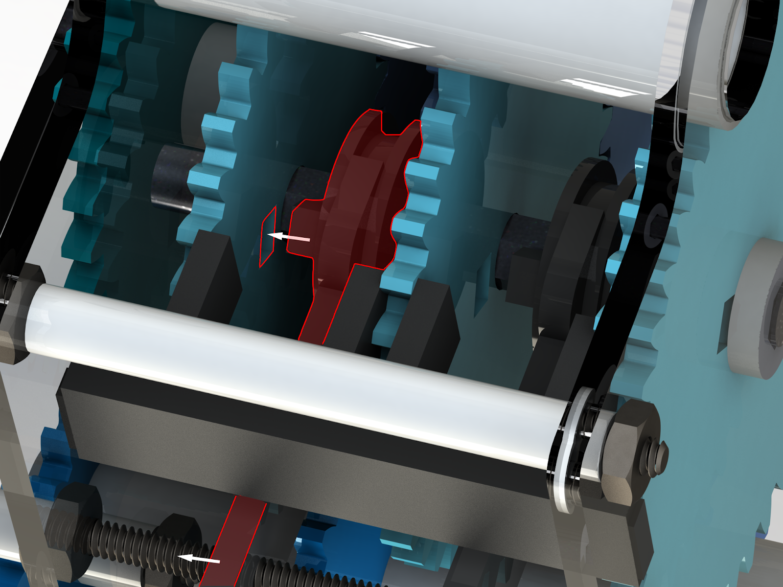
The gearbox required a converter and mount to accept power from the DC motor. The converter has a hex input on one end for the gear wall input shaft and a circular input with a key cut out on the other side for the motor shaft. The mounting wall has five holes that match up with the bolt pattern on the motor. The mounting wall also has three holes for mounting onto the gear wall. Three threaded rods were used to attach the mounting wall to the gear wall, with nuts on the ends and spacers in between to position the wall and motor.
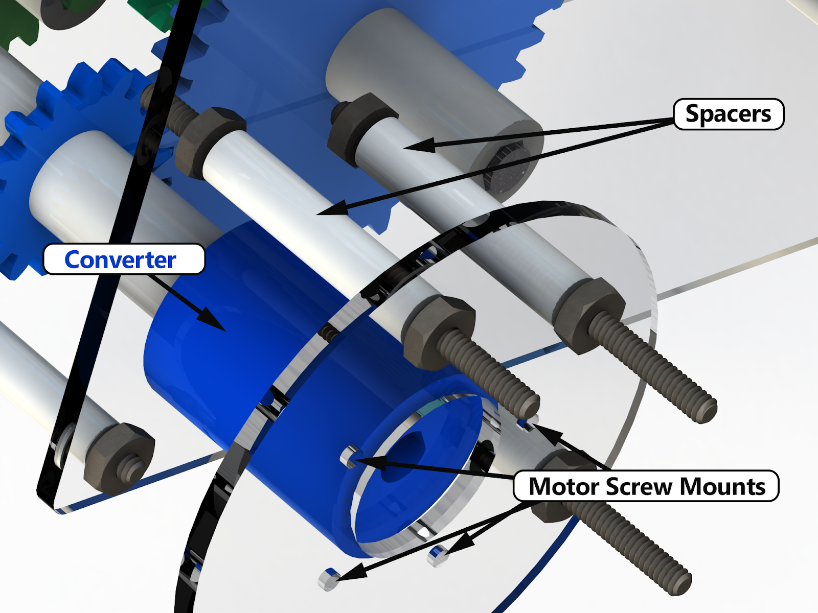
Figure 7: Motor mount apparatus.
6. Overall Summary
The motor is connected to a system of gear reductions which multiplies the final output rotation. This increases the speed of the bike. As the powertrain can shift between three “speeds”. The “speeds” are different gear reductions that serve specific purposes. One for acceleration, another to achieve top speed, and the final to maintain it with help from pedal power. Not all of the gears increase the rate of rotation. The gears designed to integrate with the rider must slow down the rotation. If you were to switch directly from motor power to pedal power, the rider would be required to pedal at a rate well in excess of anything possible by humans. To shift between the “speeds”, gears with circular centre holes were used to spin freely on the shaft. The gears also had small square holes cut out so that dog clutches could be moved between the gears and locked onto a specific gear so that the speed of that gear would be transmitted to the shaft. Only one gear should be locked onto by a dog clutch at a time, or else the gearbox will not function properly. The dog clutches are moved by wrenches that protrude from the bottom of the gearbox, which can move from side to side.
Some areas of concern for the project would be that the gearbox is made primarily out of plastic, especially in the case of the dog clutches. Since a small piece of plastic is being subjected to a bunch of shear stress at high speed, there is fear that the parts will break off. Another area that could be an issue is the tolerances of pieces and, more importantly, the gears. There is no true way of telling whether the gear teeth will mesh after being printed and put together.
Looking ahead to future projects, it would have been helpful to have known the whole scope, or larger scope, ahead of time. We found specific information, such as the tolerances for printing, that added multiple work hours to the project that may have been avoidable if known ahead of time. Not knowing some of this information also distorted the project’s scope, which could have prevented the rush to finish the project right near the deadline instead of splitting the workload into more even parts.
7. References
[1] – Balakrishnan, Nish. “MECH 2112 Project 1 – Outline.” UMLearn, University of Manitoba, https://universityofmanitoba.desire2learn.com/d2l/le/content/446933/viewContent/2857511/View?ou=446933. [Accessed 17 March, 2022]
[2] – Avdweb. Energy Requirements of Cycling. https://www.avdweb.nl/solar-bike/energy-requirements-of-cycling. 29 September, 2014. [Accessed 17 March, 2022]
[3] – Engineering ToolBox, (2008). Rolling Resistance. https://www.engineeringtoolbox.com/rolling-friction-resistance-d_1303.html [Accessed 17 March, 2022].
[4] – McGonical, Robert S. Grades and curves. Trains.com, https://www.trains.com/trn/train-basics/abcs-of-railroading/grades-and-curves/. 1 May, 2006. [Accessed 17 March, 2022]
[5] – Engineering ToolBox, (2003). Air – Density, Specific Weight and Thermal Expansion Coefficient vs. Temperature and Pressure. https://www.engineeringtoolbox.com/air-density-specific-weight-d_600.html [Accessed 17 March, 2022].
[6] – Parkin, John. Rotherham, Jonathon. Design speeds and acceleration characteristics of bicycle traffic for use in planning, design and appraisal. ResearchGate. https://www.researchgate.net/publication/223922575_Design_speeds_and_acceleration_characteristics_of_bicycle_traffic_for_use_in_planning_design_and_appraisal#:~:text=The%20power%20required%20to%20cycle,s%2C%20is%20approximately%20120%20W. September, 2010. [Accessed 17 March, 2022]
[7] – Speciale, Henry. How Much Does a Bike Weigh? – Weight of Each Bike Type. Bike To Work Day. https://biketoworkday.us/how-much-does-a-bike-weigh/#:~:text=The%20weight%20of%20your%20bike,or%20hybrid%20bikes%20with%2080lbs. 1 March, 2022. [Accessed 17 March, 2022]
[8] – Saad, Lydia. Americans’ Average Body Weight Holds Steady in 2020. Gallup, https://news.gallup.com/poll/328241/americans-average-weight-holds-steady-2020.aspx#:~:text=The%20amount%20that%20Americans%20say,overall%20average%2C%20at%20162%20pounds. 4 January, 2021. [Accessed 17, March 2021]
[9] – Wilson, David Gordon; Jim Papadopoulos (2004). Bicycling Science (Third ed.). The MIT Press. p. 44. ISBN 0-262-73154-1.
[10] – Hessemer, Dr. Rainer. Involute Spur Gear Builder v2.0. http://hessmer.org/gears/InvoluteSpurGearBuilder.html?circularPitch=8&pressureAngle=20&clearance=0.05&backlash=0.05&profileShift=0&gear1ToothCount=30&gear1CenterHoleDiamater=4&gear2ToothCount=8&gear2CenterHoleDiamater=4&showOption=3. 2020. [Accessed 17 March, 2022]
8. Appendices
8.1 Cost

8.2 Equations
[1] – Power of Wind Resistance:
Pwr = (½)(𝘱air)(Af)(Cd)(v^3)
[2] – Power of Rolling Resistance:
Prr = mg(Crr)v
[3] – Power of Gravity:
Pgr = mgsin(ⲫ)v
[4] – Total Power Required:
P = Pwr + Prr + Pgr
[5] – Conversion ratio from Angular Velocity to Torque:
R = (P / v) / n
(n = number of values/steps needed)
(v = angular velocity in rad/s)
[6] – Power in relation to Torque:
P = Tv
(v = angular velocity in rad/s)
[7] – Equation to find Velocity:
V = v x r / C
(C = reduction)